GEM IN-WHEEL ELECTRIC MOTORS ON THE RISE
18th December, 2020
Electric drive of light vehicles enables fast and pleasant drive around the city. At GEM motors, we converted the Gilera Runner 50 sr petrol scooter into an electric scooter, which is used to test GEM innovative in-wheel electric motor and a complete powertrain system. Test results on vehicles in real environment with real data help us to develop new advanced solutions and improve existing products. In addition to testing the motors, riding an electric scooter on the foothills of Kamnik Alps is simply a pleasure, and at the same time employees use it to drive to work and home and help reduce our carbon footprint.
Preparations for integration of electric powertrain
It is basically possible to integrate an electric drive to any vehicle. Before the integration it is important to have the following information:
- desired range,
- desired maximum speed
- desired climbing ability
- desired vehicle load
Based on these requirements, we select the most suitable type of GEM electric drive (in terms of power and torque) and the capacity and voltage of the battery pack. The measured data is obtained on accurate measuring equipment at our GEM motors test site in our laboratory. The key components of the powertrain are the battery management system (BMS) and the vehicle control unit (VCU) which communicate with all components and are the the heart of the propulsion system.
To ensure a complete control over the operation of the system and safe operation during the drive, we install a dedicated VCU in all vehicle conversions, which was developed and tested by our expert engineers in the field of electronics and firmware development. We pay special attention to the installation of the equipment on the vehicle, as we are aware that interventions on the vehicle affect its driving characteristics and the safe use of the vehicle. We try to replace the removed equipment of the original vehicle with an electric drive system by maintaining the weight distribution and the position of the vehicle’s centre of gravity. The battery pack is best placed towards the bottom of the vehicle since this lowers the centre of gravity and improves the stability of the vehicle.
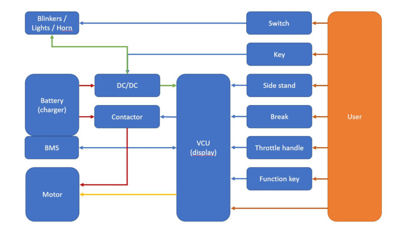
Image 1: Powertrain scheme
Integration of electric drive system
The first step was to remove the petrol engine and all associated components, leaving us with only the chassis of the vehicle with basic electrical wiring. We than adapted the developed electrical system to the chassis based on the visual layout of the components that are comprising the electrical assembly of the drive. We used the SolidWorks programme for 3D modelling of the existing chassis and then started designing the battery housing and electronics.
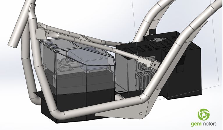
Image 2: Battery pack
Batteries usually represent the biggest cost in the conversion process, especially if we include a quality battery pack, with high capacity and a long lifespan of the product. We decided to build a battery pack with LiFePo4 cells, 40Ah capacity and a parallel connection of 15 cells. LiFePo4 cells have a long lifespan and are safe to use, their disadvantage, however, is a slightly lower energy density. The connection of the battery pack determines the rated voltage and the maximum current available to the motor, to achieve maximum power and the capacity of the pack (in kWh), which must enable desired range of the vehicle. The number of battery cells connected in series determines the voltage of the battery pack, i.e., the sum of all nominal voltages of individual batteries (e.g., 15*3.2V= 48V).
To increase the current and overall capacity, the cells need to be connected in parallel. When purchasing battery cells, it is important to take into consideration the maximum constant discharge current, usually expressed in “C”, which represents the current at which the battery is discharged in one hour.
For example, let us take a LiFePo4 cell with capacity of 20Ah and a nominal voltage of 3.2V. A mark 3C refers to the following:
- The constant discharge current is 60A
- The maximum discharge current is e.g., 5C (100A), allowed for e.g., maximum of 10 seconds
- So, if we have a 4kW motor connected to 48 V, it means that we need a battery pack that can be constantly charged with at least 84 A. When choosing the type of battery cells, we consider some current reserves to cover various losses.
The BMS is connected directly to the battery pack and its function is maintaining a balanced charge / discharge of the battery pack. We need to ensure the correct sequence of connected cells, when connecting the battery pack and the BMS.
Namely, the BMS measures the voltages of individual cells, the total current (measured on “shunt resistance”) from or into the battery pack and the temperature of the battery pack. We set charge, discharge, and load parameter limits in BMS software (e.g., maximum 3.6V per cell and minimum 2.7V, otherwise the cell may be damaged). If the battery pack overheats due to prolonged high load, the BMS switches off the supply, so the battery pack is not damaged. The BMS also interrupts charging if any of the cells reaches the minimum allowed discharge voltage or the maximum allowed charge voltage or if the battery temperature is too low.
With the use of GEM in-wheel motor G2.4, with 4kW power, the installation and connection of electronic components is easy, since all the power and control electronics is built in the motor. This solution saves space that can be used for additional battery pack and thus better range of the vehicle. Additional advantage is an easy connection of the motor to the VCU. Since all the electronics is built in the motor, we only need to connect 3 wires, two power and one signal cable. This innovative solution also reduces conductive losses on conductors.
The VCU communicates with the motor through CAN bus and sends the appropriate control commands. The VCU receives information about user’s preferences through the throttle lever, the brake button and other operating mode switches. When choosing a throttle lever, it is important to pay attention to the appropriate choice of operating range – either 0-5V or 0-12V. In addition to that the VCU also assures safe operation e.g., by detecting the position of the scooter side stand, checking the temperatures and condition of the battery pack through CAN communication with the BMS. The VCU switches on/off the main contactor, which controls the power supply to the motor. All information about the operation of the VCU system is displayed on the display and is thus constantly available to the driver.
In addition to the battery pack, BMS and VCU unit, we also installed a DC/DC converter, which is used to convert the total DC voltage of the battery pack (e.g., 48V) to 12V / DC. The DC/DC converter is used to power other electrical users on the scooter, such as indicators, horn, lights etc.
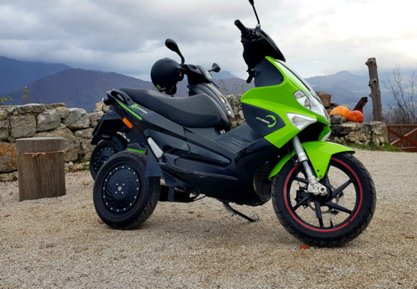
Image 3: E-scooter
Driving an electric scooter, with battery capacity of 3.2 kWh, with a range of 100 km (in “eco mode”) and a speed of up to 45 km/h (L3E) is a real pleasure, and at the same time our behaviour has a positive impact on the environment, which is also part of the company culture.
As component failures and personal injuries (cuts, electric shock, etc.) can occur during the conversion of the vehicle, we recommend that you leave the conversion to experienced professionals in the field of electrical components and connections.
Contact us for non-binding, hassle free conversation.
